
- #PICKIT 3 PINOUT FOR PIC18F SERIAL#
- #PICKIT 3 PINOUT FOR PIC18F DRIVERS#
- #PICKIT 3 PINOUT FOR PIC18F FULL#
- #PICKIT 3 PINOUT FOR PIC18F PC#
The debugger system can be configured to use standard ICSP communication for both programming and debugging functions. The debugger system configurations are discussed in the following sections.ĭo not change hardware connections while the PICkit 3 or target is powered. ☞Increased voltage range (1.8-5V VDD 1.8-14V VPP) Debugger to Target Communication ☞Extended EE program image space (512 Kbytes) ☞Provides a programmable voltage power supply The PICkit 3 differs from the PICkit 2 by providing: Similarities of the two debuggers include: The PICkit 3 programmer/debugger system is similar in function to the PICkit 2 in-circuit debugger system. ☞Resources Used by the Debugger PICkit 3VS. The basic theory of in-circuit emulation and programming is described so that problems, if encountered, are quickly resolved. It is intended to provide enough information so a target board can be designed that is compatible with the debugger for both emulation and programming operations. Table 1-1 and Table 1-2 show the support for devices and device features.Ĭ = Current support F = No support now, but planned in the future N = Support not available Note 1: This feature operates differently depending on the selected device.Ī simplified description of how the PICkit 3 programmer/debugger system works is provided here. ☞MPLAB IDE processor extension kits Device and Feature Support
#PICKIT 3 PINOUT FOR PIC18F FULL#
☞ PICkit 3 Debug Express Kit which includes: – a 44-pin demo board with a PIC18F45K20 MCU – free version of MPLAB C Compiler for PIC18 MCUs – easy-to-understand lessons and tutorials – other software utilities, examples with source code and full documentation

☞CD-ROM with MPLAB IDE software and on-line documentation.Īdditional hardware that may be ordered separately:
#PICKIT 3 PINOUT FOR PIC18F PC#
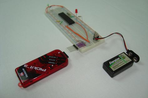
☞USB cable to provide communications between the debugger and a PC and to provide power to the debugger. ☞ PICkit 3 with indicator lights for power, activity and status. The components of the PICkit 3 programmer/debugger system are: ☞Program your device PICkit 3 programmer/debugger Components ☞Set breakpoints based on internal events ☞Debug your application on your own hardware in real time The PICkit 3 programmer/debugger allows you to: How the PICkit 3 programmer/debugger Helps You Error (red) – The PICkit 3 has encountered an error. Status: Busy (yellow) – The PICkit 3is busy with a function in progress, such as programming. Active (blue) – The PICkit 3 has connection to the PC USB port and the communication link is active.ģ. Power (green) – Power is supplied to the PICkit 3 via the USB port.Ģ. The Status LEDs indicate the status of the PICkit 3.ġ. See the pinout specification in Figure 1-2.įIGURE 1-2: PICKIT™ 3 PROGRAMMER CONNECTOR PINOUT Status LEDs The programming connector is a 6-pin header (0.100″ spacing) that connects to the target device. This marker designates the location of pin 1 for proper connector alignment. Connect the PICkit 3 to the PC using the supplied USB cable. The USB port connection is a USB mini-B connector. ☞Erase of all memory types (EEPROM, ID, configuration and program) with verificationįIGURE 1-1: PICkit™ 3 MCU PROGRAMMER/DEBUGGER Lanyard ConnectionĪ convenient lanyard connection is available on the programmer. ☞Read/write program and data memory of microcontroller ☞Built-in over-voltage/short circuit monitor

#PICKIT 3 PINOUT FOR PIC18F DRIVERS#
☞Full-speed USB support using Windows standard drivers The PICkit 3 debugger was developed for emulating embedded processors with debug facilities. All available features of a given device are accessible interactively, and can be set and modified by the MPLAB IDE interface. The debugger system executes code like an actual device because it uses a device with built-in emulation circuitry, instead of a special debugger chip, for emulation. In addition to debugger functions, the PICkit 3 programmer/debugger system also may be used as a development programmer.
#PICKIT 3 PINOUT FOR PIC18F SERIAL#
The PICkit 3 programmer/debugger is a debugger system used for hardware and software development of Microchip PIC® microcontrollers (MCUs) and dsPIC® Digital Signal Controllers (DSCs) that are based on In-Circuit Serial Programming™ (ICSP™) and Enhanced In-Circuit Serial Programming 2-wire serial interfaces. The application usage can vary from software development to hardware integration. The PICkit 3 programmer/debugger is an integral part of the development engineer’s toolsuite. The PICkit 3 programmer/debugger (see Figure 1-1) is a simple, low-cost in-circuit debugger that is controlled by a PC running MPLAB IDE (v8.20 or greater) software on a Windows® platform. ☞Device and Feature Support PICkit 3 programmer/debugger Defined ☞ PICkit 3 programmer/debugger Components ☞How the PICkit 3 Programmer/Debugger Helps You An overview of the PICkit 3 programmer/debugger system is given.


 0 kommentar(er)
